Characteristics:
|
| |
- Switches from the VSN line are cam switches with switching programmes comprised of the shape and number of cam cuts.
- The design of the switch makes it possible for two mutually independent switching circuits to be in each level.
- Circuits can be joined together by standardized couplers, both same-level and between levels.
- Switches are mounted to the panel using M4 screws according to the drilling layout specified for each type. From seven levels onward, it is recommended to mount the switch from the front and back, with respect to the mechanical strength and load from wires.
- All conducting parts are made of brass, copper or silver. Other parts are made of plastic.
- The basic design meets the IP 20 protection standard for the switch body and the IP 65 protection standard for the front sealed side with shaft.
- Switches are insulation class I and II appliance compliant.
- Cam switches can be used in control and power circuits.
- Cam switches exceeding 250 A are supplied in cooperation with KRAUS & NAIMER.
|
IP 20 protection
|
| |
- The basic design meets the IP 20 protection standard for the switch body and the IP 65 protection standard for the front sealed side with shaft. This protection is satisfied for the VSN40 through VSN150 model series once the wires are connected to terminals. If wires are not connected to some of the terminals during assembly, n order to maintain IP20 protection, the terminals of these switches without wires shall be covered with plugs that are part of the standard supply. Plugs can also be ordered separately as a spare part.
|
Switch assembly:
|
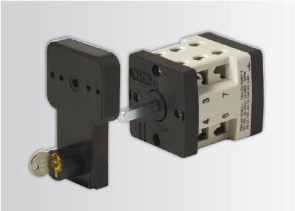
- The cam switch can be mounted by the face from the front or by the back from the back folding panel - we recommend applying this mounting only up to three levels. Switches longer than 3 levels are recommended to be mounted from the front and back folding panel simultaneously. A universal "rear anchor panel", which mounts the switch using both screws and DIN panels, can also be ordered separately. "Rear mounting" switches that are ordered already contain this universal "rear mounting panel" (including the DIN panel fixation option).
|
Use:
|
| |
- These switches are designed for common and tropical environments, with ambient temperatures of up to 55 °C.
- The manufacturer recommends using the switch included with the basic line.
- Special programmes can be established based on an agreement with the manufacturer.
- VSN10 - 16 - 20 switches are supplied with plastic covers for four levels (OK4) and up to six levels (OK6). Protection corresponds to IP54.
- VSN10 - 16 - 20 switches are supplied with the K1 cover in three versions. Protection corresponds to IP65.
- VSN25 - 32 - 40 - 63 - 75 switches are supplied with the K2 plastic cover in five versions with IP 65 protection.
- VSN80 - 100 - 125 - 150 switches are supplied with the SKN plastic cover with a maximum number of 3 levels. Protection corresponds to IP65
- In case none of the catalogue switches meet your demands, you can use the Atypical switching programme specifications form to define the desired switching programme. Please send clarification via e-mail to ots@obzor.cz.
- The production of atypical switches shall be discussed with the manufacturer.
|
| |
Method of identification:
|
| |
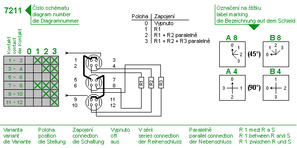
The catalogue numbers for cam switches is based on the character sequence. See the following example to achieve a better understanding:
VSN16 1103A8-V-PNC-S-201-NSC-R21 |
| |
- VSN16 - series indicating the nominal working current (in our case 16 amps)
- 1103 - wiring diagram type (switching and disconnecting individual contacts)
- A8 - indicates the basic shaft rotation positions with cams and the switching angle
- V - method of assembly to panel with plate
- PNC - front panel
- S-201 - silver plate with label 0-1
- NSC - arrow type on switch shaft
- R21 - special design with reverse to specified position
|
| |
| |
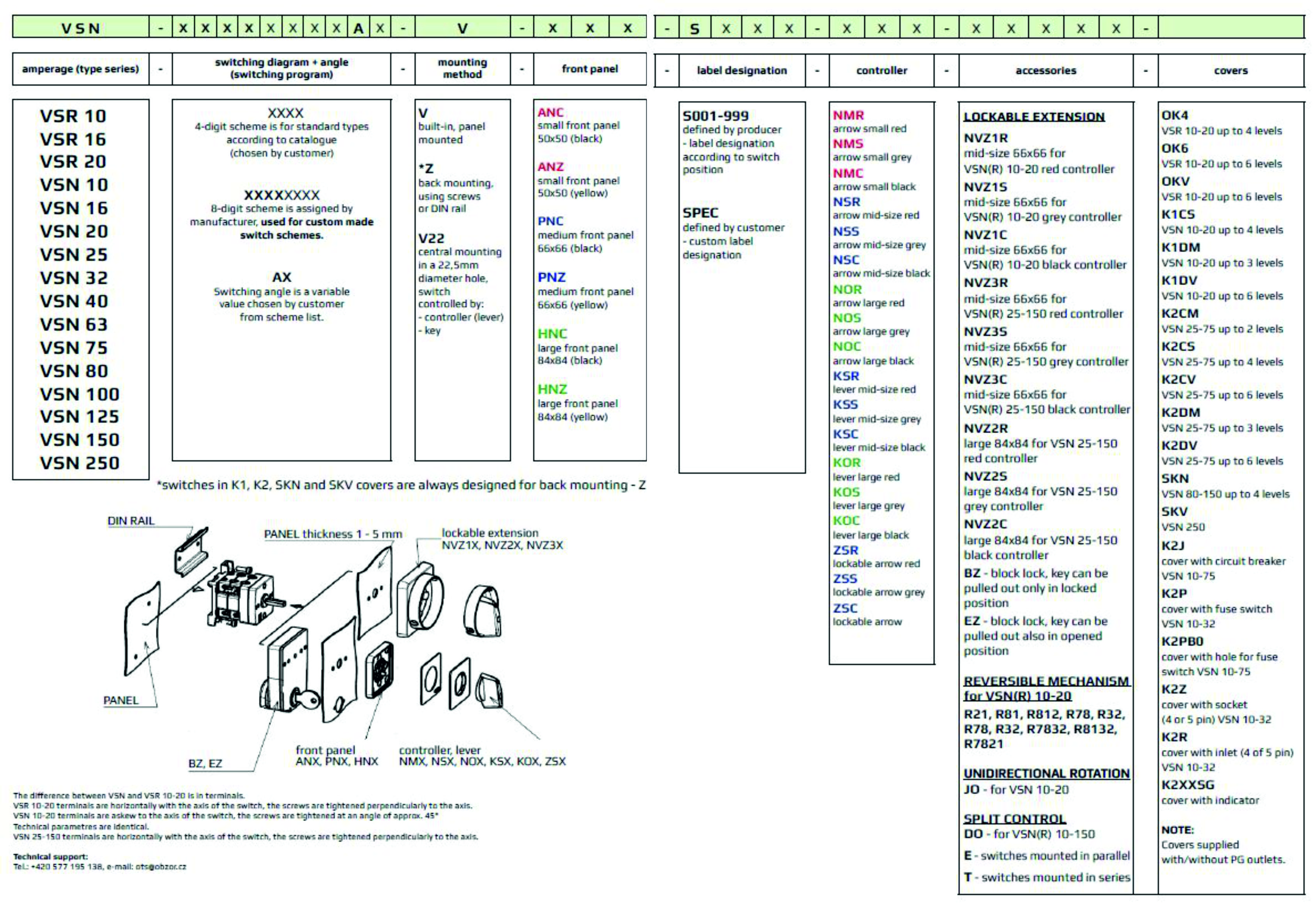 |
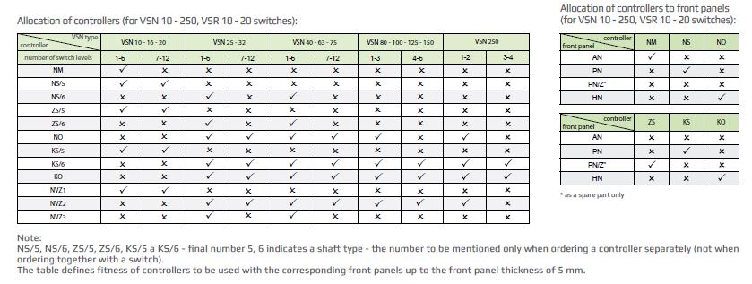
Select and specify switches based on the following steps:
- choose the nominal working current according to the basic technical data tables
- VSN10 = 10 A
- VSN40 = 40 A and others
- choose the switching diagram from chapter" diagram number"
- 1104 = four contacts switched in a cycle 0 - 1
- 9455 = single-phase motor switch and others
- choose the rotary angle and home position for the switching diagram from chapter "diagram number"
- A8 = switching angle 45 degrees, zero position at "12 o' clock"
- C1 = switching angle 30 degrees, zero position at "12 o' clock" and others
- choose the method of assembly
- V - method of assembly to panel
- Z = rear mounting of switch including mounting to DIN panel
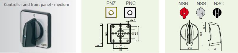
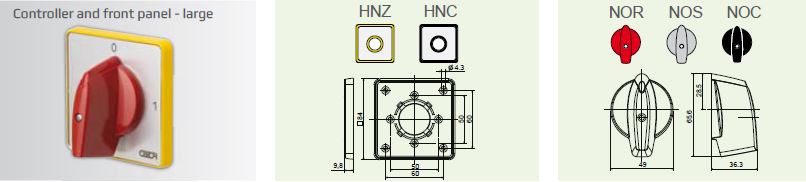
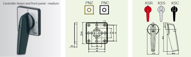
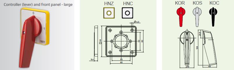
- choose the front panel
- ANC = 50x50 mm
- PNC = 66x66 mm
- HNC = 84x84 mm
- select control arrow
- NSC = medium black arrow
- NOR = large red arrow
- define accessories to cam switch
- BZ = block lock
- R21 = design with reverse
- finally, define the protective cover, if applicable
- NKV = protective plastic cover and others
/CLICK IMAGE TO ENLARGE/
|
Cam switches comply with the requirements of the ČSN EN 60 947-1 and ČSN EN 60 947-3 article 2.3 - disconnectors standards and are considered suitable for the defined external influences AB2-AB7.
All cam switches can be used for a nominal voltage of 400V AC and 500V AC.
In spite of this, however, we recommend consulting the designer when selecting cam switches for the relevant external influences.